Difference between revisions of "Modules:Editor-Documentation-3.6"
| Line 11: | Line 11: | ||
{| | {| | ||
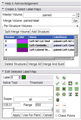
|[[Image:Editor3.6-interface.png|thumb|280px|User Interface]] | |[[Image:Editor3.6-interface.png|thumb|280px|User Interface]] | ||
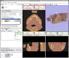
| − | |[[Image: | + | |[[Image:Slicer3.6-Editor-2010-05-06.png|thumb|280px|Output]] |
| − | |||
|} | |} | ||
| Line 68: | Line 67: | ||
==== Using the Editor Effects ==== | ==== Using the Editor Effects ==== | ||
| + | |||
| + | The individual tools in the editor are described on their own [[Modules:Editor-Documentation|Editor Documentation]] page. | ||
===Tutorials=== | ===Tutorials=== | ||
| − | |||
| − | |||
| − | |||
===Quick Tour of Features and Use=== | ===Quick Tour of Features and Use=== | ||
| Line 99: | Line 97: | ||
===Notes from the Developer(s)=== | ===Notes from the Developer(s)=== | ||
| − | + | The code makes extensive use of object oriented scripting (based on the incrTcl language). This was used primarily as a | |
===Dependencies=== | ===Dependencies=== | ||
Revision as of 21:52, 6 May 2010
Home < Modules:Editor-Documentation-3.6http://www.slicer.org/slicerWiki/index.php/Modules:Editor-Documentation
Return to Slicer 3.6 Documentation
Module Name
MyModule
General Information
Module Type & Category
Type: Interactive Scripted
Category: Base
Authors, Collaborators & Contact
- Developer: Steve Pieper: Isomics, Inc.
- Patron: Ron Kikinis: BWH
- Designer: Wendy Plesniak
- Contact: Steve Pieper, pieper at bwh dot harvard dot edu
Module Description
This is a module for manual segmentation of volumes. Some of the tools mimic a painting interface like photoshop or gimp, but work on 3D arrays of voxels rather than on 2D pixels. The overall goal is to allow users to efficiently and precisely define structures within their volumes as label map volumes. These label maps can be used for building models, or further processing (using, for example, the Label Statistics module).
Usage
Use Cases, Examples
Single Label Map
A typical straightforward Editor workflow for consists of the following steps:
- Load a volume using File->Add Volume interface.
- Enter the Editor module using either the toolbar or the Modules menu button.
- You will be prompted to select a color table to use for editing (see Color Table Dialog image).
- Pick a color node that contains the structures you wish to create. If there are no appropriate tables available, you can create custom nodes in the Colors Module.
- Clicking apply in the Color Table Dialog will create a new label map volume based on the background volume in the Red slice view at the time you entered the Editor. It will be the same dimensions, orientation, and spacing as the background volume. But it will be initialize to all zeros and it will have the 'Label Map' property set. (You can look at these in the "Info" tab of the Volumes Module.
- If your background was named 't1' the label will be called 't1-label'.
- Note that if you already have a label map volume as the result of a previous editing step it will be automatically selected when you enter the Editor (i.e. after using the Fast Marching or other Segmentation Modules you will be set up to perform manual edits of the selected label map). You can use the Set option to pick this label map instead of the default.
- Note that the background and label map settings in the Red slice viewer are used to determine the volumes to edit. In the Editor Module the background grayscale volume is known as the "Master Volume" because it is used as input to tools such as Threshold Paint. The map is known as the "Merge Volume" because it contains multiple structures (see below for information about splitting and re-merging the Merge Volume to edit individual structures).
- When label map volume is selected, the edit tools frame will automatically expand and you can use the Editor Effects to define your structures.
Per-Structure Volumes
(Please familiarize yourself with the Single Label Map approach before attempting to use the Multiple Label Map tools.)
This approach can be used to independently work with a single structure using tools like the Threshold effect that operate on the entire volume. To access this functionality, open the Per-Structure Volumes interface by clicking on the downward pointing triangle on the right side of the box.
- Start with a Merge Volume that will contain all the structures of interest.
- If you have already started defining the individual structures with different label values in the editor, or if you used something like Otsu Segmentation to generate a label map, then you can use the Split Merge Volume button to create a new volume for each unique label value in the Merge Volume.
- If you are starting from scratch, you can use the Add Structure button to define new label volumes.
- Add Structure will prompt you for a label value based on the Color Table selected when the Merge Volume was created.
- The new Structure Volume will be selected for editing.
- You can click in the Per-Structure Volumes list box to select the current label map for editing (so that you can easily toggle between the Structure Volumes).
- After defining the individual structures, you can use the Merge All button to put the volumes back into the Merge Volume.
- Use Merge And Build to create a set of modules from the merged volume.
- This uses the Joint Smoothing option of the Model Maker Module to create watertight models.
- Hint: you can use the Model Maker module to manipulate other building parameters.
- The Delete Structures button will remove the Per-Structure Volumes from your scene. If you want to delete a single volume, use the Data Module.
Using the Editor Effects
The individual tools in the editor are described on their own Editor Documentation page.
Tutorials
Quick Tour of Features and Use
A list panels in the interface, their features, what they mean, and how to use them. For instance:
|
Development
Notes from the Developer(s)
The code makes extensive use of object oriented scripting (based on the incrTcl language). This was used primarily as a
Dependencies
Other modules or packages that are required for this module's use.
Tests
On the Dashboard, these tests verify that the module is working on various platforms:
- MyModuleTest1 MyModuleTest1.cxx
- MyModuleTest2 MyModuleTest2.cxx
Known bugs
Links to known bugs in the Slicer3 bug tracker
Usability issues
Follow this link to the Slicer3 bug tracker. Please select the usability issue category when browsing or contributing.
Source code & documentation
Links to the module's source code:
Source code:
Doxygen documentation:
More Information
Acknowledgment
Include funding and other support here.
References
Publications related to this module go here. Links to pdfs would be useful.


