Modules:MainApplicationGUI-Documentation-3.6
Return to Slicer 3.6 Documentation
Contents
- 1 CURRENTLY UNDER DEVELOPMENT
- 2 Overview
- 3 Individual Panels
- 4 Application Menubar
- 5 Application Toolbar
- 6 Module GUI Panel
- 7 Slice Viewer Control Panel
- 8 3D Viewer Control Panel
- 9 Slicer Viewers
- 10 Error Log
- 11 Status Text and Progress Bar
CURRENTLY UNDER DEVELOPMENT
The dcumentation below for the main GUI of 3D Slicer version 3.6 is currently under development.
Overview
Slicer3's main desktop interface provides top-level access to most commonly-used features, and organizes them into logical groupings. These groups of features are presented in a number of interface panels on the GUI, as is illustrated in the basic layout below. The interface is designed to be easy to learn and remember, to ease navigation of Slicer's large (and growing) functionality, and to easily collapse and hide when you don't need to see it. Figures A through I in the "Individual frames" gallery a little further down on this page provide richer detail and will be described in the following sections.

As shown above, the logical groupings of Slicer's interface elements include:
- The Application Menubar
- The Application Toolbar
- The Main GUI Panel, which consists of:
- Slicer's Logo Panel
- The Module GUI Panel
- The Slice Viewer Controls
- The 3D Viewer Controls
- The 3D Viewer
- Three Main Slice Viewers (Red, Yellow, and Green)and additional Slice Viewers
- The Message Bar and Progress Gauge
- And the Error Log Button
An overview of the functionality provided in each of these interface elements is provided below.
Individual Panels
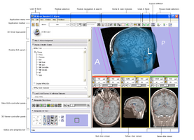
Figure A. Schematic of the main application GUI
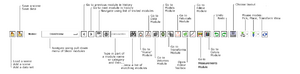
Figure B. Schematic of the Application Toolbar
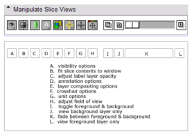
Figure C. Schematic of the Controller for all Slice Viewers
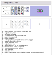
Figure D. Schematic of the Controller for the 3D Viewer
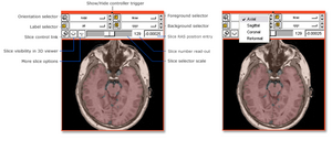
Figure E. Schematic of a Slice Viewer and Slice Controller
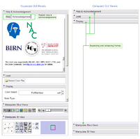
Figure F. Schematic of an expanding/collapsing module GUI panel
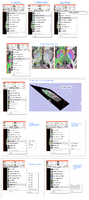
Figure G. Schematic of Slice Viewer additional options
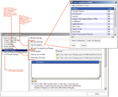
Figure H. Schematics of the Application Settings Interface
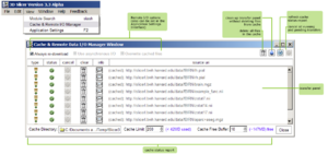
Figure I. Schematic of the Remote Data Handling Interface


Application Menubar
The Application menubar is at the very top of Slicer3's main window, as noted above and in Figure A. Its menus and functionality are briefly listed below.
Several loading options are available from the file menu. Below is a general overview of these options. For more details and suggestions for common use cases, see Data loading details for Slicer3.6. For information about accessing the functionality described below and loading other types of data (like transforms, fiducial lists, color tables, DTI fiber bundles etc.) through the Data Module, see Slicer's Data Module documentation.
File->Load Scene:
This command raises a file browser (shown below). Slicer's file browser has a 'favorites' icon that allows you to save often-visited directories on the browser's left panel. Other features, including icons that allow you to navigate your browsing history, pop up a level in the directory structure (or folder hierarchy) and create new folders. To load a scene, navigate to a file of the appropriate format (.mrml, .xcat (XCEDE catalog file), or .xml (Slicer2 scene file) and select it for loading into Slicer. The command first clears any existing scene in Slicer and resets the application state.

File->Import Scene:
This command raises the same file browser shown above. Navigate to and select a scene file to be added to the existing Slicer scene. (The existing scene is not cleared).
File->Add Data:
This command raises an "Add Data" widget (shown below) that allows you to select individual datasets to add to the existing scene. This load option is most useful when you want to load many different data types at once (volumes, models, etc.) which may not yet be described by a scene file. It exposes the following functionality:
- The "Add Directory" button adds all files within the selected directory to the file list.
- The "Add File(s)" button adds all selected files to the file list.
- The array of buttons across the top allow you to select and deselect files in the file list, remove selected files from the list, or describe how files should be loaded.
- The "Apply" button loads all datasets in the list, and
- The "Cancel" button aborts the entire load.

File->Add Volume:
This command raises an "Add Volume" widget (shown below) that allows you to select a volumetric dataset to add to the existing scene. The "Volume Options" panel can be used to clarify how a selected dataset should be loaded and displayed. This load option is particularly useful for loading DICOM data, for which its DICOM information parsing panel can be helpful.

File->Save:
This command displays the "Save Data" widget, which offers many options for saving a scene and/or individual datasets. The widget is shown below:

Specifying a scene file to save: The Scene Description entry is always listed in the top row of the table. If a scene has already been loaded from a MRML file, then its filename is presented as the default choice. To save the scene into a new MRML file, either provide an alternate file name, or provide a new Data Directory.
Indicating new and unsaved datasets: When the panel is first displayed, all datasets which have been newly created or modified since the scene was saved are checked by default in the Save column. Any datasets in the scene can be checked/unchecked for saving/not saving using the checkboxes provided in this column. The icon buttons in the top left corner (from left to right) of the window provide shortcuts to modify the default selection:
- Select Scene and Modified Data,
- Select Modified Data only,
- Select All, and
- Select None.
These icons are shown and annotated below, under the SaveData illustration. Any individual checkbox can also be used to modify the selection state.

Converting to other data formats: Any dataset can be converted to a different (supported) format by editing the filename extension. Note that some format conversions may be lossy. To change formats, select from the list provided in the File Format column. A dataset's filepath and filename may be edited to save the dataset in a location different from that specified.
Supported formats: Formats that can be saved include:
- Volumes
- NRRD (.nrrd)
- NRRD (.nhdr)
- MetaImage (.mhd)
- MetaImage (.mha)
- VTK (.vtk)
- Analyze (.hdr)
- Analyze (.img)
- Analyze (.img.gz)
- BMP (.bmp, .BMP)
- BioRad (.pic)
- Brains2 (.mask)
- GIPL (.gipl, .gipl.gz)
- JPEG (.jpg, .jpeg, .JPG, .JPEG)
- LSM (.lms, .LSM)
- NifTI (.nia)
- NifTI (.nii, .nii.gz)
- PNG (.png, .PNG)
- Stimulate (.spr)
- TIFF (.tiff, .tif, .TIFF, .TIF)
- Models
- Poly Data (.vtk)
- XML Poly Data (.vtp)
- STL (.stl)
- Fiducials
- Fiducial List CSV (.fcsv)
- Text (.txt)
- Transforms
- Transform (.tfm)
- Text (.txt)
Saving data: Finally, selecting the Save Selected button will launch the scene/data saving process, and Cancel will abort it.
File->Close Scene:
This command closes the current scene and resets the application state.
File->Exit
This command exits Slicer.
Edit->Set Home
This command sets a user's 'home module', which is the module displayed by default each time the Slicer application is started. The home module is saved in the Application Registry.
Edit->Undo
This command undoes the history of undoable commands, from last to first.
Edit->Redo
This command re-does the history of commands most recently undone, from last to first.
Edit->Edit Box
This command raises the Edit-box, a lightweight image editing tool.
Edit->New Fiducial List
This command creates a new list of fiducial points.
View->Manage Extensions:
This Extensions Management Wizard provides status and information about available extensions for 3.6
View->Cache & RemoteIO Manager:
The Cache and Remote Data Handling interface provides status and information about all remote data transfers, and allows some control over the local cache. Remote I/O and Cache preferences can also be set in the Application Settings Interface, described next. Whether you set preferences here or there, they are saved in the Application Registry so that your settings are preserved each time you start up the Slicer Application.
The pop-up interface is shown below. Checkbuttons at the top left provide choices about download and caching behavior, and the cache directory, cache size limit, and cache free space buffer can be set at the interface bottom. Icon buttons at the top right allow global operations on all data transfers (cache clearing and transfer cancellation) and display updates (transfer panel cleanup and cache report refreshing). Each data transfer is listed in the transfer panel along with some information about its type and status.

Below, all of the Cache & Remote Data I/O Manager icons are listed and described:

View->Application Settings Interface:
The Application Settings interface provides options for saving many of Slicer's Interface and Remote Data Handling options to the Application Registry, so they are preserved across sessions. The first time you start the application, it is recommended that you browse these settings and select options that you prefer. Some of the options provided in the interface are listed below:
- Slicer Settings allow you to specify whether Slicer should confirm on delete, and set the location for other applications that Slicer may need to use (Firefox, Zip, etc.).
- Font Settings options allows you to choose among several fonts and relative font sizes to be displayed in the GUI.
- Module Settings options allow you to select a Temporary directory, a home module (that will be displayed each time Slicer starts up) and whether Slicer should include loadable and command-line modules on startup.
- Remote Data Handling Settings options allow the specification of Cache and Remote Data I/O settings which are also configurable from the Cache and Remote Data I/O Manager described above.

Window->Hide/Show Main Panel (Hotkey = F5):
This command collapses or expands the GUI panel and allows Slicer's viewers to occupy the entire application window, as shown below in Application Layouts figure C.
Window->Hide/Show Bottom Panel (Hotkey = F6):
This command collapses or expands the bottom split-panel in which Slice viewers are conventionally displayed, allowing the 3D view to occupy the vertical extent of the application window. The behavior of this command will vary, and may not be appropriate, depending on the selected layout (-- available layouts are described below.)
Window->Toolbars:
This command allows hiding or exposing sub-toolbars in the application toolbars, including the Load/Save toolbar, the undo/redo toolbar, the layout configuration, and the mouse mode toolbar.
Window->Log Window (Hotkey = Ctrl+Alt+E):
This command raises the error log display.
Window->Tcl Interactor (Hotkey = Ctrl+T):
This command raises the Tcl interactor for scripted interaction with Slicer data:

Help->Browse Tutorials:
Raises Slicer's training page in mozilla firefox web browser (Note: you will need to have specified the location of Mozilla Firefox executable in Slicer's Application Settings Interface: Application Settings->Slicer Settings).
Help->About Slicer3:
Provides a description of the Slicer3 effort and its support.
Help->Keyboard Shortcuts:
Raises a window that lists commonly-used keyboard shortcuts.
Note: for all commands in the Feedback Menu, you will need to have specified the location of your Mozilla Firefox executable in Slicer's Application Settings Interface: Application Settings->Slicer Settings) so Slicer knows how to launch the web browser.
Feedback->Report a Bug:
This command opens your Firefox web browser to http://www.na-mic.org/Bug/my_view_page.php so that any bug you encounter can quickly and easily be reported. Be sure to select the appropriate category for the bug and estimate its severity. It's recommended that you provide as much information as you can so that the bug can be reproduced by the development team.
Feedback->Report a Usability Issue:
This command opens your Firefox web browser to http://www.na-mic.org/Bug/my_view_page.php so that any usability issue you encounter can quickly be captured. Be sure to select the "usability" category for the issue and estimate its severity. We request that you describe the way in which the usability issue is impacting your work so that the usability and development team can address the issue appropriately. Suggestions and ideas are welcome!
Feedback->Make a Feature Request:
This command opens your Firefox web browser to http://www.na-mic.org/Bug/my_view_page.php so that community feature requests can easily be collected. We request that you clearly mark your submission as a "feature request" in the description field of the form.
Feedback->Community:
This command opens your Firefox web browser to http://www.slicer.org/slicerWiki/index.php/Slicer3:VisualBlog where you can post screenshots of interesting ways you are using the Slicer3 software package in your research and share them with the Slicer community.
Application Toolbar
Slicer's toolbar provides quick access to centralized load / save functionality, options for searching for and navigating among modules, undo/redo capability, ability to select different application layouts and change among mouse modes. Using and indicating mouse modes in Slicer is still under development, so this part of the toolbar will likely change in future releases. For now, "Mouse place" is used to create new objects, like fiducial points. "Mouse pick" is intended for selecting objects. "Transform view" is the default mode, used to pan, zoom and rotate the camera in the 3D viewer. Individual icons in the toolbar are labeled below.

The Window->Toolbars submenu allows showing/hiding parts of this toolbar, including the Load/Save toolbar, the undo/redo toolbar, the layout configuration, and the mouse mode toolbar.
Module GUI Panel
Conventions and window position:
By default, the Module GUI panel is located on the left of the application window. The panel that contains the Module GUI, Slices Control GUI and 3D Viewer Control GUI (both described below) can be moved to the right side also by selecting that option from the layout menu on the toolbar, if that working configuration is found to be more convenient. Each Slicer module populates the Module GUI panel with its interface; all modules have a Help & Acknowledgement frame that presents brief help text and pointers to additional information, and appropriate acknowledgement for the work as shown in the figure below.
Collapsing and expanding frames:
Each module GUI contains its functionality inside collapsing and expanding frames, also shown below, to minimize the need to scroll among individual blocks of functionality within a module. The frames can be collapsed or expanded by clicking in the title frame. The Slices Control and 3D Viewer Control GUI panels also can be collapsed to make more space for a module GUI.
Brief Help Text and Module Attribution and Acknowledgements can be found in the topmost panel in any module.

Slice Viewer Control Panel
The Slice Viewer Control Panel allows configuration of all Slice GUIs at once. The functionality represented by icons in Slicer Version 3.6 is described below:

3D Viewer Control Panel
The 3D Viewer Control Panel provides many options for configuring the 3D viewer. The left-most panel allows the view to be oriented along any of the six principle axes (Superior, Inferor, Anterior, Posterior, Left or Right). Axis symbols highlight on mouse-over. The functionality included in the panel represented by icons and checkboxes is described in the diagram below. Finally, the rightmost viewer duals as a birds-eye-view display of the entire scene, or a slice magnifier window when the mouse moves over any of the slice windows.

Stereoscopic and Kinetic Depth
The 3D Viewer provides a number of options for assessing depth and layout in complicated scenes. The stereo viewing pull-down menu, labeled "M" in the schmatic above, provides several stereo viewing options, and the view rock (labeled "O") and view spin (labeled "N") animate the scene to help clarify feature shape, depth and layout.
Screen Captures ("Screenshots")
Screen captures of the 3D Viewer can be saved by selecting the icon labeled "D" in the schematic above. This raises the Screen Capture interface (shown below) that allows you to specify a save destination, a filename, version number, image format and exposes the option for overwriting existing files.

Scene Snapshots
Scene snapshots provide a way to record particular compositions of a scene. These compositions are saved with the scene and can be restored for later inspection. Among the things recorded in each snapshot are:
- Model visibility,
- Volume display threshold, window and level settings,
- Slice visibility in the 3D view.
To create or restore a scene snapshot:
- Click on the camera icon (labeled "H" in the schematic above) to record a scenesnapshot.
- Use the pull down menu (labeled "L" in the schematic above) to select from a list of existing snapshots.
- Click on the arrow icon to restore the snapshot.
- You can also click on the trashcan icon to delete the snapshot.

Slicer Viewers
In this section, Slicer's Slice Viewers and Main 3D Viewer are described, and options for configuring their layout and display of information.
Slice Viewers (and their Controllers)
Slicer's three main Slice Viewers are color-coded Red, Yellow and Green. By default, these correspond to Axial, Saggital and Coronal slice orientations respectively, but this can be modified by a user. In Slicer's Compare View layout (described a little later), the Slice Viewers are color-coded Orange.
All Slice viewers have their own Slice Controller, which can be expanded or collapsed by clicking in the colored bar at their top, for convenience. The Red Viewer is shown below, expanded and collapsed as described. Note that corner annotations are displayed when the mouse hovers over any viewer.

The Slice GUI Controller provides ways to manipulate its individual Slice View, and provides ways to manipulate all "linked" Slice Viewers. Below is a schematic of the individual controls provided with each Slice Viewer; these, and "linked" control are described (briefly) in subsequent sections.

Slice orientation and Oblique reformats
On each Slice Viewer, an Orientation menu button in the upper left of the control panel provides the option to display an "Axial", "Coronal", "Sagittal", or "Reformat" slice orientation in the Viewer.
Slice viewers can be used to specify oblique reformats in two ways:
- first by using the "Reformat" orientation and CTRL-Right-Button-Move (subject to change and something of an "art" to control).
- and second by selecting the Show Reformat Widget option (
 ) from the Slice Controller's More Options menu (
 ), and interacting with the widget. The widget can be toggled off using the menu's Hide Reformat Widget option (
 ). Using this widget's interactive box & arrow to reformat the slice plane (illustrated below) causes the Orientation selector to display the "Reformat" orientation, and the Slice Viewer to display the reformatted plane.
Note: Reformat widgets are like pop-up menus - their on/off state is not saved in the MRML scene or in scene snapshots. The orientation of the oblique reformat is saved in the scene.

Linking Control of Slice Viewers
Control of slice viewers can be linked to save time setting them up and manipulating their display individually. The icons shown below, found in the leftmost of each Slice Controller's toolbar, toggle linking and unlinking of the viewers.
![]()
When Slice Viewers are linked, the "linked" icon (![]() )is displayed. Clicking the icon-button will unlink the Viewers, and will display the "Unlinked" icon (
)is displayed. Clicking the icon-button will unlink the Viewers, and will display the "Unlinked" icon (![]() ). When the Slice Viewers are linked, many but not all of the controllers' options apply to all viewers. The following controls are linked:
). When the Slice Viewers are linked, many but not all of the controllers' options apply to all viewers. The following controls are linked:
- Orientation
- FG, BG, Label selectors
- Visibility
- Fit To Window
- Adjust Label Map Opacity
- Show/Hide Label Volume Outlines
- Show/Hide Reformat Widget
Slice Plane Visibility in 3D Viewer
The Slices shown in each of the Slice Viewers may be displayed in the Main 3D Viewer as well. Their visibility in the 3D Viewer is controlled with the Visibility icon button in the Slice Controllers, as shown in the figure below. When Slices are visible in the 3D Viewer, the "visible" icon (![]() )is displayed. Clicking the icon-button will hide the Slices in the 3D Viewer, and will display the "Invisible" icon (
)is displayed. Clicking the icon-button will hide the Slices in the 3D Viewer, and will display the "Invisible" icon (![]() ).
).

Other Slice GUI options
The Slice controllers offer other options as well, available under the More Options menubutton (![]() ). Options here include some of those available in the Slices Controller GUI and some additional. These options, each shown in the figures A - I below, include:
). Options here include some of those available in the Slices Controller GUI and some additional. These options, each shown in the figures A - I below, include:
- A. Fit a slice to the size of a Viewer's window
- B. Change orientation to match the Volume plane
- C. Adjust the opacity of a label map
- D. Show/Hide outlines around labels in a label map
- E. Show/Hide the Slice Reformat Widget
- F. Select options for compositing slice layers
- G. Choose manual or automatic slice spacing modes
- H. Create a lightbox view within a Slice Viewer
- I. Adjust the display of Foreground, Background or Label layers.

Configuring Slice Viewers when the Controllers are collapsed
In Slicer's Slices Module, all Slice Viewers' Slice Controllers are arrayed in a vertical stack; When screen real estate must be maximized, the individual Slice Viewers' Controllers can be collapsed and the GUI panel's controllers can be used to manipulate the Viewers instead. The Slices Module's GUI panel is shown below.

Main 3D Viewer
Default elements and their visibility
Slicer's Main 3D Viewer displays a three-dimensional view of the scene. By default, the scene includes some elements for spatial reference including a 3D wireframe cube centered around the origin (0,0,0) and labels along each of the principle axes (Right, Left, Superior, Inferior, Anterior, and Posterior). Slicer's default blue background color, as well as the visibility of the spatial references in the view, can be modified in the View Control GUI panel's visibility menu, as shown below:

Interacting
You can adjust the view in the Main 3D Viewer using the mouse or keyboard (for information on the latter, please see the Keyboard Shortcuts section):
- Zoom in: Right-mouse-button click-and-drag toward you. (Imagine pulling the scene closer)
- Zoom out: Right-mouse-button click-and-drag away from you. (Imagine pushing the scene away)
- Pan (shift the look-at point): Middle-mouse-button click-and-drag left, right, up or down.
- Rotate Around a look-at point: Left-mouse-button click-and-drag.
If you need more precise control, or if the view gets into some hard-to-manage configuration, the View Control GUI panel can be used to reset the look-from and look-at point in a manageable way:

GUI Panel Configurations
Slicer can be configured to show or hide the Module GUI panel, and to display it on the left or right side of the Viewers. These options are accessed as follows:
- Show/Hide Module GUI Panel: F5-key or Toolbar's Layout Menubutton (
 )->Toggle GUI panel visibility
 - Move Module GUI Panel to the Left/Right: Toolbar's Layout Menubutton ()->Toggle GUI panel L/R
- Show/Hide Bottom Panel: F6-key (this option is only really useful in Slicer's Conventional View)

Selecting Among Standard Layouts
In addition, there are a number of ways to arrange the Slice and 3D Viewers. We hope to offer a more extensible suite of configuration options in the future. At present, these options are available from Slicer's Application Toolbar's Layout Menubutton (![]() ), and are illustrated below:
), and are illustrated below:

Notes about Multiple 3D Views
Slicer 3.6 contains partial support for multiple 3D views, but many of the slicer tools such as Measurements are only visible in the main view (the view on the left in the Dual 3D View layout).
Error Log
Finally, the application has an accessible error log in the event of unexpected behavior or error messages -- this readout is useful for reporting bugs or usability problems back to the Slicer Development Team. The error log can be raised in the following ways:
- Typing Ctrl+Alt+E
- Menubar's Window->Error Log
- Clicking the Error Log icon, which is displayed only if any error reports are present, and as shown below.


Status Text and Progress Bar
For some operations, loading, saving or processing may take awhile; Slicer may post status text at the bottom of the Application's window (shown below) that helps you to understand what it's working on. This readout isn't available as often as it should be; we hope to address this usability issue in future software releases. If you encounter any situation in which a status update would be especially useful but none exists, please report your discovery to Slicer's bug tracker as a usability issue.

Progress is also displayed during processing operations. One progress readout commonly used by command-line modules is found in the lower right corner of the Slicer Window in the Progress Gauge, shown below:

Some Slicer modules also use a pop-up progress dialog, which assumes "focus" and prevents you from interacting with Slicer until the processing is finished; the dialog appears as below:
