Slicer3:openIGT Tutorial For 4D Volume Rendering Data
From Slicer Wiki
Home < Slicer3:openIGT Tutorial For 4D Volume Rendering Data
This tutorial will teach you how to setup Slicer3 and an image provider to send and display 4D image data. The theory is described on Slicer3:4DUltrasound 4D US
Contents
Prepare Slicer3
Downloading and Compiling the source
- Download and compile a copy of Slicer3 as described in Slicer3:Build_Instructions.
- !! use http://www.na-mic.org/svn/Slicer3/branches/igt_cuda_merge as the source !!
Setting up the 3D Slicer
- Start up Slicer3
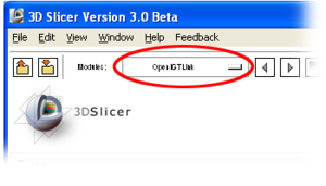
- Select the OpenIGTLink Module from the Modules Tab.
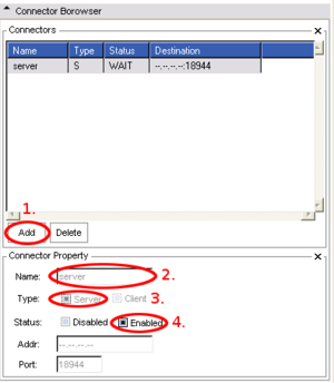
- Start the server, by clicking on the Connector Browser Tab.
- Add a Server
- Select a Name (optional)
- Set the type to server
- Enable the server by setting the status to 'Enabled'.
Get IP-Address of the Slicer Computer
Store the IP-Address of the computer. This is done by 'ipconfig' on Windows and 'ifconfig' on UNIX.
Prepare the Image Provider
Downloading and Compilation
- Check out the Server code from http://www.na-mic.org/svn/NAMICSandBox/trunk/BRPTools/ScannerIO
svn co http://www.na-mic.org/svn/NAMICSandBox/trunk/BRPTools/ScannerIO
- Compile the Code
   cmake .
   make
- Download the data package with ct-scans of a human heart and unzip it into the source directory
Start the Scanner-Simulator
- start the scanner with the Arguments:
 Usage: ./bin/ScannerSim <x> <y> <z> <type> <rx> <ry> <rz> <fname_temp> <bindex> <eindex> <fps> <hostname>
   <x>, <y>, <z>   : Number of pixels in x, y and z direction.
   <type>          : Type (2:int8 3:uint8 4:int16 5:uint16 6:int32 7:uint32
   <rx>, <ry>, <rz>: resolution (pixel size) in x, y and z direction
   <fname_temp>    : File name template (e.g. "RawImage_%04d.raw").
   <bindex>        : Begin index.
   <eindex>        : End  index.
   <fps>           : Frame rate (frames per second).
   <hostname>      : hostname (port# is fixed to 18944)
- For the heart dataset the following will do:
./bin/ScannerSim 256 256 256 3 1 1 1 heart256-%d.raw 1 5 10 [Slicer-IP-Address]
Check Connection
- The Provider should now transfer images to Slicer3 (should be running)
- In Slicer3 go to the Data Module
- In the Display & Modify Scene section should now be a new node called Scanner(vtkMRMLScalarVolumeNode1).
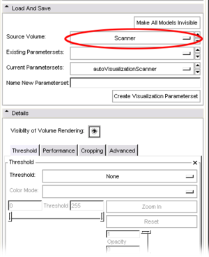
- Select the module VolumeRendering.
- You can now choose Scanner as Source Volume


