Modules:VMTKCenterlines
Return to Slicer 3.6 Documentation
Module Name
VMTKCenterlines, part of the  collection
General Information
Module Type & Category
Type: Scripted Module
Category: Segmentation, Extension
Authors, Collaborators & Contact
- Author: Daniel Haehn, University of Heidelberg
- Acknowledgments: Luca Antiga, Mario Negri Institute; Steve Pieper, Isomics Inc.
- Contact: Daniel Haehn, haehn@bwh.harvard.edu
Module Description
This module provides centerline computation of surface models in 3D Slicer using methods of the geometric analysis functionality of the Vascular Modeling Toolkit (http://www.vmtk.org). Centerlines are the central lumen lines in tubular structures and f.e. can be powerful descriptors of the vessel's topology. The module targets easy-to-use centerline extraction using seed and target points and also enables import and export functionality.
The actual centerline extraction is based on calculating an inner Voronoi diagram by computing the Delaunay tessellation.
This work is part of the NA-MIC VMTK Collaboration.
Official project page: http://www.vmtk.org/Main/VmtkIn3DSlicer
Usage
Installation
This module depends on the VmtkSlicerModule: see this page for installation notes.
The VMTKCenterlines module can be installed using the 3D Slicer extension wizard. The extension is called VMTKCenterlines.
When the module was successfully installed, it is available within 3D Slicer's module selector inside the category Vascular Modeling Toolkit.
Examples, Use Cases
- Example centerline extraction
The centerline computation requires an existing 3D surface model. This can be obtained using the VMTKEasyLevelSetSegmentation module.
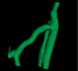
After selecting the existing surface model as input, the second step is to prepare this model. This includes capping holes in the surface and removing unneeded triangles. The surface model color changes to green.
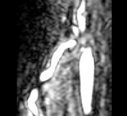
 A surface model of a segmentation of the original image obtained with the VMTKEasyLevelSetSegmentation module. |
Now source and target fiducials have to be placed on the model in the 3D rendering window to specify the centerline routes. The fiducial positioning does not have to be exact because the module calculates the nearest position on the surface model to the input fiducials. After placing the fiducials, the centerline computation can be started. Depending on the surface model size the process can take a couple of minutes.
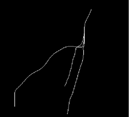
On completion of the calculation, the inner Voronoi diagram and the corresponding centerlines are visible as polydata models in the 3D rendering window.
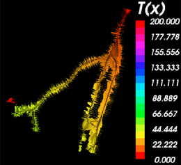 The inner Voronoi diagram colored by the solutions of the Eikonal equation obtained by Fast Marching back-tracking along the minimal path. The legend can be displayed using the Colors module. |
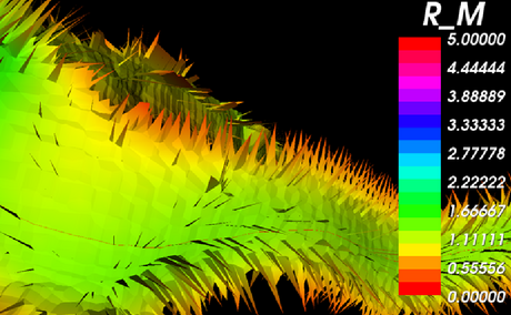
A close-up of the Voronoi diagram shows the tiles separating the Voronoi regions. The modules also calculates the radius of the lumen for each point along the centerlines.
The extracted centerlines as well as the calculated radii along the centerlines can be exported and imported as a cloud of points to the filesystem.
Tutorials
The following tutorials demonstrate the use of VMTKCenterlines in a pipeline of VMTK modules to extract the centerlines of coronary arteries.
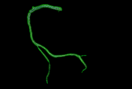 Step-by-step online tutorial: Segmentation of the Right Coronary Artery using VMTK in 3D Slicer. View online here. |
 Step-by-step tutorial including example dataset: The first slide of the Centerline Extraction tutorial. Download here. |
Quick Tour of Features and Use
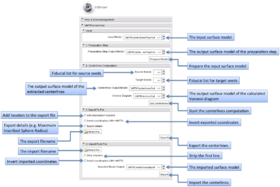
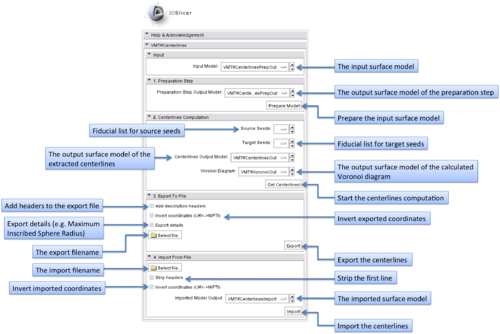
The graphical user interface of the VMTKCenterlines module consists of five panels.
- Input panel:
The input surface model can be selected using this panel.
- Preparation Step panel:
The preparation step includes surface capping and removing unneeded traingles of the input model.
- Centerline Computation panel:
This step includes the actual centerline extraction. Source and target points can be specified as fiducial lists. At least one source and one target point have to exist but it is possible to use f.e. only one source point and several target points. The centerlines run between these points.
Additionally the output models for the centerlines and the Voronoi diagram can be specified.
- Export panel:
The module supports the export of the extracted centerlines as cloud of points to the filesystem. It is possible to add a header to these files or additional details like the radii. Inverting the coordinates multiplies the X,Y coordinates by -1.
- Import panel:
Exported centerlines (clouds of points) can be imported as surface models.
Development
Notes from the Developer(s)
The algorithms provided by VMTK and used by this module are C++ classes implemented using VTK and ITK. More information on Voronoi diagrams can be found on Wikipedia (http://en.wikipedia.org/wiki/Voronoi_diagram). The algorithm using the minimal path on this diagram is described in Luca Antiga's PhD thesis (http://villacamozzi.marionegri.it/~luca/files/AntigaPhDThesis.pdf).
Dependencies
This module depends on the VMTK libraries which are provided in the VmtkSlicerModule. Therefore the VmtkSlicerModule has to be installed before the VMTKCenterlines module can be used.
Known bugs & Usability issues
Follow this link to the VMTK in 3D Slicer bug tracker.
Source code & documentation
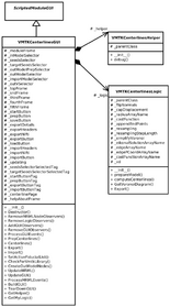
VMTKCenterlines is a Python Scripted Module. It follows the conventions of the Model View Controller pattern of slicer modules. This implies the separation of logic and GUI.
The class VMTKCenterlinesGUI derives from ScriptedModuleGUI and saves the current parameters to its own MRML node. The actual calls to the VMTK libraries as well as the import and export functionality are performed in the class VMTKCenterlinesLogic. Several general supporting functions are outsourced in the class VMTKCenterlinesHelper.
The complete source code is available at a NITRC SVN repository.
More Information
Acknowledgment
This work was funded by a grant of the Thomas-Gessmann Foundation part of the Founder Federation for German Science.
References
- Antiga L, Piccinelli M, Botti L, Ene-Iordache B, Remuzzi A and Steinman DA. An image-based modeling framework for patient-specific computational hemodynamics. Medical and Biological Engineering and Computing, 46: 1097-1112, Nov 2008.
- D. Hähn. Integration of the vascular modeling toolkit in 3d slicer. SPL, 04 2009. Available online at http://www.spl.harvard.edu/publications/item/view/1728.
- D. Hähn. Centerline Extraction of Coronary Arteries in 3D Slicer using VMTK based Tools. Master's Thesis. Department of Medical Informatics, University of Heidelberg, Germany. Feb 2010.
- Piccinelli M, Veneziani A, Steinman DA, Remuzzi A, Antiga L (2009) A framework for geometric analysis of vascular structures: applications to cerebral aneurysms. IEEE Trans Med Imaging. In press.
