Home < Modules:Measurements-Documentation-3.6Return to Slicer 3.6 Documentation
Gallery of New Features
Measurements
Measurements
|
|
|
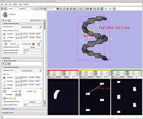 Using a ruler to measure between points on a model, and an angle to measure between points on a model |
General Information
Module Type & Category
Type: Interactive
Category: Base
Authors, Collaborators & Contact
- Nicole Aucoin (3D): BWH
- Steve Pieper (2D): BWH
- Karthik Krishnan and Will Schroeder: Kitware
- Contact: Nicole Aucoin, nicole@bwh.harvard.edu
Module Description
The Measurements module allows you to add rulers and angle widgets to the scene and they will be displayed and able to be manipulated in both the 3D and 2D windows.
Usage
A ruler can be created between fiducial points by pressing Control-m .
In order to get the end points of the ruler or the angle to move along a selected model surface, you currently need to rotate the view so that the handle is rendered on top of the model, the next click will snap it to the model surface. If you move the model or slice plane, the measurement point won't move with it, the constraint only works when moving the end point handle. If you make the model or slice invisible, the end point cannot be moved, as the constraint will always be false.
When you add a new angle or affine transform widget, you have to click once in the 3D window to render the transform widget, and three times to place the angle widget end points. After that, you can move the widgets around by dragging the handles.
Use Cases, Examples
This module is especially appropriate for these use cases:
- Use Case 1: Useful for measuring tumor diameters.
- Use Case 2: Measuring angles between bones.
Examples of the module in use:
- Example 1: Place two fiducial points, press Control-m to create a new ruler between the fiducials, and then the two fiducials.are deleted. A name can be given to add to the ruler annotation text. Uses the last two selected fiducials of the active fiducial list.
- Example 2: Attach/constrain end points of the widgets to volume slices to measure distances and angles between image features.
- Example 3: Attach/constrain end points of the widgets to models to measure distances and angles between 3D structures.
Tutorials
Links to tutorials explaining how to use this module:
Quick Tour of Features and Use
- Ruler Widget panel:
- Modify All Ruler Nodes panel
- Select the visibility of all ruler nodes. Set all rulers invisible or set all rulers visible.
- Delete all ruler nodes from the scene.
- Generate Report: saves basic information about all rulers in the scene to a file on disk (distance, position, annotation). If a CSV (comma separated value) format is chosen, the information is separated by commas, if .txt is chosen, the information is separated by tabs.
- Modify Selected Ruler Node panel
- Ruler Node Select: create a new ruler node, show the parameters of a previously created ruler node, delete or rename a ruler node
- Distance: the distance between the end points of the current ruler, updated as the end points move.
- The next two rows of icons correspond to the two end points:
- End Point Color: set the color used to show the ruler end point
- Constraint: constrain the motion of the ruler end point to be on the surface of the selected model or volume slice plane. In order to get the end points of the ruler to move along a selected model surface, you currently need to rotate the view so that the handle is rendered on top of the model, the next click will snap it to the model surface. If you move the model or slice plane, the measurement point won't move with it, the constraint only works when moving the end point handle. If you make the model or slice invisible, the end point cannot be moved, as the constraint will always be false.
- Position: ruler end point positions, updates when the ruler handles are moved in 3D or 2D, and can be used to update the end points by typing in a value.
- Display Options
- Visibility: if the eye is open, this ruler is visible, if it is closed, this ruler is invisible. Click on it to toggle the state.
- Line Color: set the color used to show the ruler line
- Annotation Color: set the color used to show the distance annotation text
- Distance Annotation Visibility: if the eye is open, show the distance in mm between the end points along the line, if the eye is closed, hide the distance annotation text. Click on the icon to toggle the state.
- Standard Annotation Formats: a drop down menu allowing you to choose standard formatting strings for the annotation text. It will over ride any current entries in the Distance Annotation Format box.
- 1 decimal
- 0 decimals
- 2 decimals
- Scientific Notation
- Distance Annotation Format: how to display the distance annotation, use string formatting strings, %g for an auto formatted floating point, %.2f to show two decimal places. Any text is allowed, defaults to mm (millimeters). Please see the following link for more info about formatting options.
- Distance Annotation Scale: how large to render the distance annotation text
|
|
- Angle Widget panel:
- Modify All Angle Nodes panel:
- Select the visibility of all angle nodes. Set all angles invisible or set all angles visible.
- Delete all angle nodes.
- Modify Selected Angle Node panel:
- Angle Node Select: create a new angle node, show the parameters of a previously created angle node, delete or rename an angle
- Angle: the angle between the rays of the current ruler, updated as the end points move. In degrees.
- The next three rows of widgets refer to the three end points that make up the angle, first, center, second:
- Set End Point Color: set the colour used to show the angle end point
- Constraint: constrain the motion of the angle end points to be on the surface of the selected model or volume slice plane. In order to get the end points of the angle to move along a selected model surface, you currently need to rotate the view so that the handle is rendered on top of the model, the next click will snap it to the model surface. If you move the model or slice plane, the measurement point won't move with it, the constraint only works when moving the end point handle. If you make the model or slice invisible, the end point cannot be moved, as the constraint will always be false.
- Position: angle point positions, updates when the angle handles are moved in 3D, and can be used to update the points by typing in a value.
- Display Options:
- Visibility: if the eye is open, this angle is visible, if it is closed, this angle is invisible. Click on it to toggle the state.
- Line Color: set the color used to show the angle lines
- Text Color: set the color used to show the angle annotation text
- Ray visibility: toggle visibility for the two rays that make up the angle. If the eye is open, this ray is visible, if it is closed, this ray is invisible. Click on it to toggle the state. The first ray is from the first point to the center point, the second ray is from the second point to the center point.
- Arc Visibility: If the eye is open, show the arc between the two angle arms. If it is close, the arc is invisible. Click on it to toggle the state.
- Arc Color: set the color used to show the arc between the rays.
- Standard Annotation Formats: a drop down menu allowing you to choose standard formatting strings for the annotation text. It will over ride any current entries in the Distance Annotation Format box.
- 0 decimals
- 1 decimal
- 2 decimals
- Angle Annotation Format: how to display the angle annotation, use string formatting strings, %g for an auto formatted floating point, %.2f to show two decimal places. Any text is allowed after the numerical specification. The angle is in degrees. Please see the following link for more info about formatting options.
- Angle Annotation Scale: how large to render the angle annotation text
|
|
Development
Notes from the Developer(s)
- This module was added at version 3.5, and expanded at version 3.6, and it will not work unless Slicer3 is compiled with VTK5.6 or higher.
Dependencies
No other modules or packages are required for this module's use.
Tests
On the Dashboard, these tests verify that the module is working on various platforms:
Known bugs
Links to known bugs in the Slicer3 bug tracker:
Usability issues
Follow this link to the Slicer3 bug tracker. Please select the usability issue category when browsing or contributing.
Source code & documentation
Measurements source code
Documentation generated by doxygen:
More Information
Acknowledgment
This work is part of the National Alliance for Medical Image Computing (NAMIC), funded by the National Institutes of Health through the NIH Roadmap for Medical Research, Grant U54 EB005149.
References


