Documentation/Nightly/Modules/AstroSmoothing
|
For the latest Slicer documentation, visit the read-the-docs. |
Introduction and Acknowledgements
|
Authors: Contributors: Acknowledgements: Contacts:
|
Module Description
The AstroSmoothing module contains a set of filters aimed to denoise astronomical (HI) dataset:
- Anisotropic Box;
- Anisotropic Gaussian;
- Intensity-driven Gradient.
These algorithms are available in SlicerAstro as parallelized implementations on both CPU and GPU hardware, offering interactive performance when processing data-cubes of dimensions up to 107 voxels and very fast performance (< 3.5 sec) for larger ones (up to 108 voxels).
The intensity-driven gradient filter, due to its adaptive characteristics, is the optimal choice for HI data (see [1]). Therefore, it is the default method when the automatic mode has been chosen. This algorithm preserves the detailed structure of the signal with high signal-to-noise ratio (> 3) at the highest resolution, while smoothing only the faint part of the signal (signal-to-noise ratio < 3). For more information regarding the filters and their performance, default parameters, advantages and disadvantages, we refer to [2].
Panels and their use

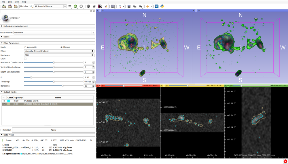
A comparative layout of the output generated by the AstroSmoothing module is shown. The interface includes a widget for changing the input parameters for the smoothing and a table showing the output segmentations generated after the smoothing process. This includes the widgets for changing the input (such as the filter choice, the computational hardware and the smoothing parameters) and visualizing the output segmentation objects generated by the smoothing process. The comparative layout is composed of two 3D views and three 2D views. In the left 3D view and the 2D views the data are shown. In the right 3D view the filtered version of the data is shown. The data are rendered in different colors that highlight the data at different intensity levels: green, blue and red correspond to 3, 7 and 15 times the rms noise respectively. The colored segmentations represent masks automatically calculated by the filtering algorithm. The light blue and yellow segmentations (visualized as contour plots in the 2D views) are a 3 rms thresholding of the input data and the filtered data, respectively.
References
@ARTICLE{2016A&C....17..163P,
   author = {{Punzo}, D. and {van der Hulst}, J.~M. and {Roerdink}, J.~B.~T.~M.
	},
    title = "{Finding faint H I structure in and around galaxies: Scraping the barrel}",
  journal = {Astronomy and Computing},
archivePrefix = "arXiv",
   eprint = {1609.03782},
 primaryClass = "astro-ph.IM",
 keywords = {Radio lines: galaxies, Techniques: image processing, Scientific visualization},
     year = 2016,
    month = oct,
   volume = 17,
    pages = {163-176},
      doi = {10.1016/j.ascom.2016.09.002},
}
