Home < Documentation < 4.4 < Modules < MeshCompression
Introduction and Acknowledgements
|
Extension: CBC 3D I2MConversion
Acknowledgments:
- This work was partially supported by NIH R44 OD018334-03A, grant CCF-1139864 and by the Richard T.Cheng Endowment.
Author: Fotis Drakopoulos
Contributors: Fotis Drakopoulos (CRTC), Yixun Liu (CRTC), Andrey Fedorov (CRTC), Nikos Chrisochoides (CRTC)
Contact: Nikos Chrisochoides, <email>npchris@gmail.com</email>
Website: https://crtc.cs.odu.edu
License: BSD
|
| Center for Real-time Computing
|
|
|
Module Description
The Mesh Compression (MC) module deforms the input tetrahedral mesh towards the boundaries of the input labeled image. Two point sets are extracted for the mesh deformation. The first (source point set) consists of the surface vertices in the input mesh. The second (target point set) consists of the surface edge points in the input labeled image. After the extraction of the two point sets, the input mesh is deformed by registering the source to the target point set using a Physics-Based Non-Rigid Registration method. The current version of the module supports a single-tissue labeled image and mesh.
Use Cases
|
|
|
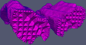
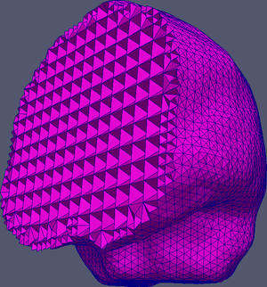 Brain BCC mesh after MC (cross-section) |
|
|
|
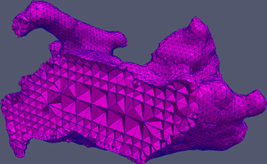 Nidus BCC mesh after MC (cross-section) |
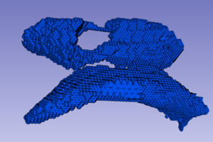 Ventricles BCC mesh before MC |
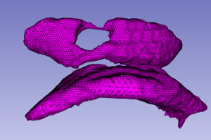 Ventricles BCC mesh after MC |
 Ventricles BCC mesh after MC (cross-section) |
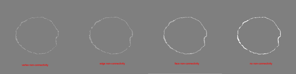 How the non-connectivity parameter influences the number of the extracted target points |
Tutorials
N/A
Panels and their use
- Mesh Compression Parameters:
- Flexibility: Controls the trade-off between the regularization energy defined by the stress energy of a linear bio-mechanical elastic model, and the similarity energy. Value should be between [0.1,1] (default: 1).
- Number of Iterations: Controls the number of iterations for the compressor. The larger the value the closer the boundaries of the input mesh to the boundaries of the input image. A large number of iterations might cause distorted poor-quality elements. Value should be between [1,10] (default: 3).
- Non Connectivity: Controls the density of the extracted target points via a prohibited connectivity between adjacent blocks of voxels. The larger the value the denser the target point set. 0 is vertex non-connectivity (26 neighbors), 1 is edge non-connectivity (18 neighbors), 2 is face non-connectivity (6 neighbors) and 3 is no non-connectivity. Value should be 0 or 1 or 2 or 3. (default: 0).
- Input/Output:
- Input Labeled Image: The input labeled image.
- Input Mesh File: The input tetrahedral mesh in vtk file format.
- Output Mesh File: The output deformed mesh in vtk file format (optional) (default: deformedMesh.vtk).
- Output Source Points File: The extracted source points in vtk file format (optional). The source points are the surface vertices of the input mesh.
- Output Target Points File: The extracted target points in vtk file format (optional). The target points are the surface edge points of the input labeled image.
- Output Surface Triangles File: The extracted surface triangles of the input mesh in vtk file format (optional).
|
|
Note: this module will only work if the input image has identity orientation!
Similar Modules
References
- Yixun Liu, Panagiotis Foteinos, Andrey Chernikov and Nikos Chrisochoides, "Mesh Deformation-based Multi-tissue Mesh Generation for Brain Images", Engineering with Computers, Volume 28, pages 305-318, 2012.
Information for Developers


