Difference between revisions of "Documentation/Nightly/Modules/CornerAnnotation"
| (52 intermediate revisions by the same user not shown) | |||
| Line 8: | Line 8: | ||
{{documentation/{{documentation/version}}/module-introduction-start|{{documentation/modulename}}}} | {{documentation/{{documentation/version}}/module-introduction-start|{{documentation/modulename}}}} | ||
{{documentation/{{documentation/version}}/module-introduction-row}} | {{documentation/{{documentation/version}}/module-introduction-row}} | ||
| − | This work is supported by NA-MIC, NCIGT, Slicer Community | + | This work is supported by Shiga University of Medical Science (SUMS) in Japan, NA-MIC, NCIGT, and Slicer Community. |
<!-- This work is part of the National Alliance for Medical Image Computing (NA-MIC), funded by the National Institutes of Health through the NIH Roadmap for Medical Research, Grant U54 EB005149. Information on NA-MIC can be obtained from the [http://www.na-mic.org/ NA-MIC website].<br> --> | <!-- This work is part of the National Alliance for Medical Image Computing (NA-MIC), funded by the National Institutes of Health through the NIH Roadmap for Medical Research, Grant U54 EB005149. Information on NA-MIC can be obtained from the [http://www.na-mic.org/ NA-MIC website].<br> --> | ||
| − | Author: Atsushi Yamada | + | Author: Atsushi Yamada (SUMS)<br> |
| − | Contributors: Junichi Tokuda ( | + | Contributors: Junichi Tokuda (BWH), Koichiro Murakami (BWH, SUMS), Soichiro Tani (SUMS), Shigeyuki Naka (SUMS), Tohru Tani (SUMS)<br> |
Contact: Atsushi Yamada, <email>ayamada@belle.shiga-med.ac.jp</email><br> | Contact: Atsushi Yamada, <email>ayamada@belle.shiga-med.ac.jp</email><br> | ||
| + | License: [http://www.slicer.org/pages/LicenseText Slicer License] | ||
| + | |||
{{documentation/{{documentation/version}}/module-introduction-row}} | {{documentation/{{documentation/version}}/module-introduction-row}} | ||
{{documentation/{{documentation/version}}/module-introduction-logo-gallery | {{documentation/{{documentation/version}}/module-introduction-logo-gallery | ||
| − | |Image:SumsLogo2014.jpg|Shiga University of Medical Science | + | |Image:SumsLogo2014.jpg|Shiga University of Medical Science (SUMS) in Japan |
|{{collaborator|logo|namic}}|NA-MIC | |{{collaborator|logo|namic}}|NA-MIC | ||
|{{collaborator|logo|ncigt}}|NCIGT | |{{collaborator|logo|ncigt}}|NCIGT | ||
| Line 25: | Line 27: | ||
{{documentation/{{documentation/version}}/module-section|Module Description}} | {{documentation/{{documentation/version}}/module-section|Module Description}} | ||
{| | {| | ||
| − | |[[File: | + | |[[File:CA-1.png|460x640px]] |
| − | |||
| − | |||
|} | |} | ||
| + | |||
{| | {| | ||
| − | |[[File: | + | |[[File:CA-UI3.png|460x760px]] |
| − | |||
| − | |||
|} | |} | ||
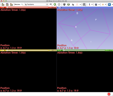
| + | The CornerAnnottion module is a Slicer4 module designed to display annotations, time count, node elements on each panels (3D, Red, Yellow and Green views, respectively) on the Slicer user interface. | ||
| + | You can edit annotations, display panels, font style, color, and opacity, respectively. | ||
| − | |||
| − | |||
| − | |||
| − | |||
| − | |||
| − | |||
| − | |||
| − | |||
<!-- | <!-- | ||
Here comes a description what the module is good for. Explain briefly how it works and point to the [[documentation/{{documentation/version}}/Modules/{{documentation/modulename}}#References|references]] giving more details on the algorithm. | Here comes a description what the module is good for. Explain briefly how it works and point to the [[documentation/{{documentation/version}}/Modules/{{documentation/modulename}}#References|references]] giving more details on the algorithm. | ||
| Line 52: | Line 45: | ||
<!-- ---------------------------- --> | <!-- ---------------------------- --> | ||
| − | {{documentation/{{documentation/version}}/module-section|Use Cases}} | + | {{documentation/{{documentation/version}}/module-section|Use Cases}} |
| − | + | {| | |
| − | + | |[[File:CornerAnnotationModuleSS.png|460x760px]] | |
| − | + | |} | |
| − | + | ||
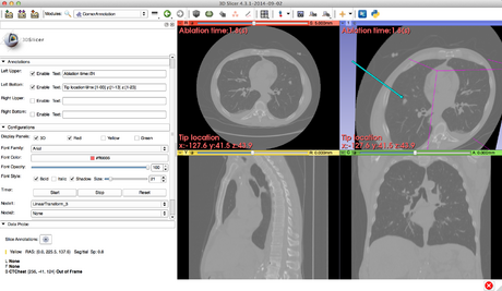
| − | + | The CornerAnnotation module allows to display any texts you create at any corners on your Slicer viewers. Furthermore, you can also display a timer count and elements of transform matrixes you set. | |
| + | Therefore, you can use this module, for example, to alert a surgeon to an ablation time and to indicate the tip of the tracker for quantitative assessment attractively in image guided therapy. | ||
| + | We hope this module can help 3D Slicer to be used as a navigation system. | ||
<!-- ---------------------------- --> | <!-- ---------------------------- --> | ||
| Line 66: | Line 61: | ||
{{documentation/{{documentation/version}}/module-section|Panels and their use}} | {{documentation/{{documentation/version}}/module-section|Panels and their use}} | ||
{| | {| | ||
| − | |[[ | + | |[[File:CA-UI1.png|460x640px]] |
|} | |} | ||
| − | + | * Annotations panel | |
| − | * | + | ** This module allows to create four annotations: Left Bottom, Left Upper, Right Bottom and Right Upper. Each Enable button display each text you created. |
| − | ** | + | **Text format |
| − | + | ***@n: start a new line | |
| − | ** | + | ***@t: display timer |
| − | *** | + | ***[3-10]: Element(1,0) of Node3 |
| − | |||
| − | *** | ||
| − | ** | ||
| − | |||
{| | {| | ||
| − | |[[ | + | |[[File:CA-UI2.png|460x660px]] |
|} | |} | ||
| − | |||
| − | |||
| − | |||
| − | |||
| − | |||
| − | |||
| − | |||
| − | |||
| − | |||
| − | |||
| − | |||
| − | |||
| − | |||
| − | |||
| − | |||
* Configurations panel | * Configurations panel | ||
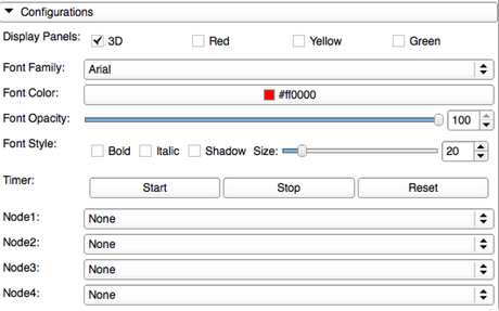
| − | ** | + | **Display Panels check boxes can enable annotations you created to display on 3D, Red, Yellow, and Green views respectively. |
| + | **Font Family selector can change font style. | ||
| + | **Font color selector can change font color. | ||
| + | **Font opacity slider bar can change opacity for displayed annotations. | ||
| + | **Font Style | ||
| + | ***Bold, Italic, Shadow checkboxes can change the font style of the annotations. | ||
| + | ***Size slider bar can change font size. | ||
| + | **Timer | ||
| + | ***Start button can start the timer. | ||
| + | ***Stop button can stop the timer count. | ||
| + | ***Reset button can reset the timer count. | ||
| + | ***Description | ||
| + | ****You can display timer count by typing "@t" in the annotation texts. | ||
| + | **Node selectors | ||
| + | ***There are four node selector. You can select Transform Node you created by using Transform module. | ||
| + | ***Description | ||
| + | ****You can display the transform element (0,2) of Node1 by typing "[1-02]" in the annotation texts. | ||
| + | ****You can display the transform element (0,1) of Node2 by typing "[2-01]" in the annotation texts. | ||
<!-- | <!-- | ||
| Line 109: | Line 102: | ||
<!-- ---------------------------- --> | <!-- ---------------------------- --> | ||
{{documentation/{{documentation/version}}/module-section|References}} | {{documentation/{{documentation/version}}/module-section|References}} | ||
| − | *[ | + | *[https://github.com/ayamada0614/CornerAnnotation Github source code repository] |
| − | *[ | + | *Transform module |
| + | *[http://openigtlink.org/ OpenIGTLinkIF module] | ||
| + | |||
| + | <!-- ---------------------------- --> | ||
| + | {{documentation/{{documentation/version}}/module-section|Logo}} | ||
| + | {| | ||
| + | |[[File:CornerAnnotationIcon.png|128x128px]] | ||
| + | |} | ||
| + | |||
<!-- ---------------------------- --> | <!-- ---------------------------- --> | ||
Latest revision as of 08:35, 3 December 2014
Home < Documentation < Nightly < Modules < CornerAnnotation
|
For the latest Slicer documentation, visit the read-the-docs. |
Introduction and Acknowledgements
|
This work is supported by Shiga University of Medical Science (SUMS) in Japan, NA-MIC, NCIGT, and Slicer Community. Author: Atsushi Yamada (SUMS) | |||||||
|
Module Description

|

|
The CornerAnnottion module is a Slicer4 module designed to display annotations, time count, node elements on each panels (3D, Red, Yellow and Green views, respectively) on the Slicer user interface. You can edit annotations, display panels, font style, color, and opacity, respectively.
Use Cases

|
The CornerAnnotation module allows to display any texts you create at any corners on your Slicer viewers. Furthermore, you can also display a timer count and elements of transform matrixes you set. Therefore, you can use this module, for example, to alert a surgeon to an ablation time and to indicate the tip of the tracker for quantitative assessment attractively in image guided therapy. We hope this module can help 3D Slicer to be used as a navigation system.
Tutorials
N/A
Panels and their use

|
- Annotations panel
- This module allows to create four annotations: Left Bottom, Left Upper, Right Bottom and Right Upper. Each Enable button display each text you created.
- Text format
- @n: start a new line
- @t: display timer
- [3-10]: Element(1,0) of Node3

|
- Configurations panel
- Display Panels check boxes can enable annotations you created to display on 3D, Red, Yellow, and Green views respectively.
- Font Family selector can change font style.
- Font color selector can change font color.
- Font opacity slider bar can change opacity for displayed annotations.
- Font Style
- Bold, Italic, Shadow checkboxes can change the font style of the annotations.
- Size slider bar can change font size.
- Timer
- Start button can start the timer.
- Stop button can stop the timer count.
- Reset button can reset the timer count.
- Description
- You can display timer count by typing "@t" in the annotation texts.
- Node selectors
- There are four node selector. You can select Transform Node you created by using Transform module.
- Description
- You can display the transform element (0,2) of Node1 by typing "[1-02]" in the annotation texts.
- You can display the transform element (0,1) of Node2 by typing "[2-01]" in the annotation texts.
Similar Modules
N/A
References
- Github source code repository
- Transform module
- OpenIGTLinkIF module
Logo
Information for Developers
| Section under construction. |


