Documentation/4.3/Modules/VisuaLine
|
For the latest Slicer documentation, visit the read-the-docs. |
Introduction and Acknowledgements
|
This work is supported by NA-MIC, NCIGT, and the Slicer Community. | |||||||
This project is supported by National Institute of Health (5P01CA067165, 5R01CA124377, 5R01CA138586, 2R44DE019322, 7R01CA124377, 5R42CA137886, 8P41EB015898). |
Module Description
VisuaLine allows users to display lines on Slicer. The main purpose of this module is to visualize needle trajectories as well as targets and cross-section along the needle path. Visualization is available on 3D view, and projections of lines and targets in 2D viewers. Each trajectory have independent properties, such as turn on/off visibility of the path/target, virtual offset, and control projection properties. Trajectories could also be modified in real time. This option allow the user to check intraoperatively for example, is this new path is safe before inserting needle. VisuaLine does NOT allow creation of new trajectories. It only allows visualization of already existing rulers. However, PathPlanner module allows users to create new trajectories.
Use Cases
VisuaLine could be used for needle insertion like biopsies, but also for planning intervention, to find the optimal path to reach a target. By allowing reslicing along the trajectory path, it is possible to check if trajectory cross vital area or organs. With intraoperative images, it is also possible to overlay image and trajectory in order to verify current path is following planned path. By modifying in real-time the path, it is also possible to explore new path during surgery.
Tutorials
N/A
Panels and their use
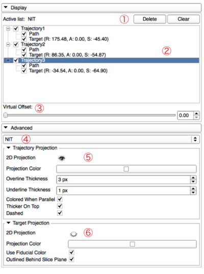
As shown on the screenshot, there is two main parts in the GUI:
- The display part
- The advanced part (collapsed by default)
Here is a description of items:
- Delete and clear buttons are used to remove one (the selected line) or everything from the list
- The list of trajectories with their path and target. Select a line to display their projection properties in items 5 and 6. Check/Uncheck elements to show/hide them.
- When a line is selected, a virtual tip could be set by using the slider to change the length of the virtual offset.
- This item allow the users to choose which list of ruler nodes will be used to populate the list (item 2)
- This group of widgets contains line projection properties of selected trajectory (on item 2), which are:
- Color (change color of the line)
- Colored when parallel to plane (e.g. colored in green if parallel to green plane)
- Thicker on top of plane ( the part of the line on top of the plane is displayed thicker than the part under. Both thickness could be adjusted)
- Dashed or plain line
- This group of widgets contains fiducial projection properties of selected trajectory (on item 2), which are:
- Color (if not using option below)
- Use fiducial color (use the same color for the projection than the fiducial)
- Outlined behing slice plane (different representation if the fiducial is in front or below slice plane)
Similar Modules
N/A
References
PathPlanner module allows users to create trajectories that could be visualized with VisuaLine module.
Information for Developers
| Section under construction. |


