|
This work is supported in part by the National Institute of Health (R01CA111288, P01CA067165, P41RR019703,P41EB015898, R01CA124377, R01CA138586, R42CA137886, and
U54EB005 149) and is funded by KUKA Laboratories GmbH (Augsburg, Germany).
Authors: Sebastian Tauscher, Junichi Tokuda
Contact: Sebastian Tauscher, <email>sebastian.tauscher@imes.uni-hannover.de</email>, Insitute of Mechatronics Systems, Leibniz University Hannover
Module Description
The LightWeightRobotIGT module allows to communicate with a light weight robot (LWR iiwa, KUKA Laboratories GmbH, Germany, Augsburg) using an open interface concept based on the OpenIGTLink protocol (LWROpenIGTIF). Therefore, a state machine example is available at Git Hub containing the necessary interface classes for the communication on the robot control. A tutorial on how to set up the robotic system for the use with this 3D Slicer module see LightWeightRobotIGT Getting Started. For an introduction of the interface concept see LightWeightRobotIGT Introduction. The module provides the following features:
- Communication with the robot control
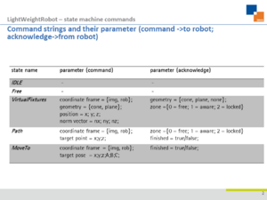
- Bidirectional cyclic communication via ethernet with a state control running on the robot control. Command strings of the type "CommandName;p1;...;pn;" with the parameters p1-pn needed to initialise the states are sent to the robot control and acknowledge strings are received (see table below for a list of all supported command and acknowledge strings and their parameters).
- Receiving the transformation matrix containing the pose of each robot joint in robot base coordinate frame and a matrix containing a similar transformation including information about the force direction, absolute value, and application point.
- Sending the transformation matrix describing the transformation from robot base coordinate frame to image space or to CT base coordinate frame
- Visualisation
- A 3D model of the robot can be loaded and is automatically connected to the corresponding transformation matrices received from the robot control.
- The estimated force at the tool center point, e.g. the tool tip, can be visualized by a scaled 3D arrow in the force direction.
- The color of the robot model changes due to the current robot state received in the acknowledge string and, hence, gives a direct feedback to the user of the current robot state
- Active virtual fixtures in relation to the robot and the target region changing their color to red when robot reach the fixtures
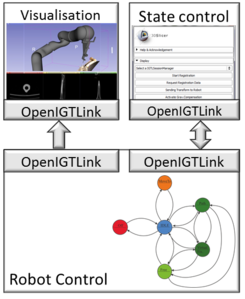
| Interface concept for the integration of a robot into an image-guided therapy system consisting of a visualization and state control
|
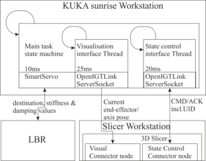
| Overview of the communication structures and the threads on the robot control and the slicer workstation
|
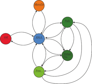
| Exemplary state machine for IGT
|
| Command and acknowledge parameter set of the exemplary state machine
|
|
Use Cases
N/A
Tutorials
Panels and their use
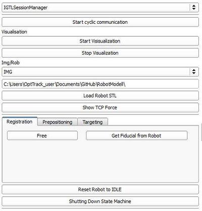
- Start Cyclic Communication: Starts the cyclic communication with the state machine on the robot control
- Start Visualisation: Sends a command to the robot control to activate the visualization
- Stop Visualisation: Sends a command to the robot control to deactivate the visualization
- Img/Rob: Changes the coordinate frame of the robot pose send from the robot control to image space or robot base frame
- Path: Path were the robot stl files are located
- Load Robot STL: Loads the stl-files of the robot and the tool from the path defined by "Path".
- Show TCP Force: Visualizing the estimated force at the tool center point by a scaled 3D arrow pointing in force direction.
- Registration tab:
- Free: Sends a transition request to the Free state to the robot control, in which the robot can be moved freely and manually
- Get Fiducial from Robot: Saves the current position in a fiducial list which can be used for a fiducial registration using modul XY
|
|
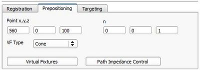
- Prepositioning tab:
- point x,y,z: Position of the cone tip or the plane in robot base coordinate frame
- n: z-axis of the cone or norm vector of the plane
- VFtype: Here you can choose the geometry of the virtual fixture - cone or plane
- Virtual Fixture: Sends a transition request to the VirtualFixtures state to the robot control in which the robot can be moved freely and manually in work space restricted by active constraints. The supported virtual fixtures geometries are plane and cone.
- Path Impedence Control: Sends a transition request to the Path state to the robot control, in which the robot can be moved on a linear path from the current position towards a target position.
|
|
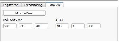
- Targeting:
- Move To Pose: Sends a transition request to the MoveTo state to the robot control in which the robot moves position controlled towards a target position.
- point x, y, z: Target position in robot base coordinate frame
- A, B, C: Euler ankle describing the orientation at the target point in robot b ase coordinate frame of the tool
- Reset Robot to Idle: Sends a transition request to the Idle state to the robot control
- Shut Down State Machine: Sends a command to shut down the state machine running on the robot control
|
Similar Modules
N/A
References
- Tauscher S, Tokuda J, Schreiber G, Neff T, Hata N, Ortmaier T. OpenIGTLink interface for state control and visualisation of a robot for image-guided therapy systems. Int J Comput Assist Radiol Surg. 2014 Jun 13.
- Tauscher S, Ortmaier T, Neff T. Interface concept for the integration of a robot into an image-guided therapy system. Proceedings of the 27th International Congress on Computer Assisted Radiology and Surgery (CARS 2013)
Information for Developers
|
