Documentation/4.6/Modules/SegmentEditor
|
For the latest Slicer documentation, visit the read-the-docs. |
Introduction and Acknowledgements
|
This work is part of the SparKit project, funded by An Applied Cancer Research Unit of Cancer Care Ontario with funds provided by the Ministry of Health and Long-Term Care and the Ontario Consortium for Adaptive Interventions in Radiation Oncology (OCAIRO) to provide free, open-source toolset for radiotherapy and related image-guided interventions.
| |||||||
|
Module Description
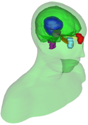
This is a module for segmentation of volumes. Segmentations (also known as contouring) delineate structures of interest. Some of the tools mimic a painting interface like photoshop or gimp, but work on 3D arrays of voxels rather than on 2D pixels. This module is the successor to the Editor module. The Segment Editor contains many of the same functionalities and more.
It is important to remember that Segment Editor does not edit labelmaps, as Editor does. It edits segmentations, and many of the new features and differences are due to using the uses the Segmentation infrastructure.
New features include:
- Overlapping segments
- Conversion to model representation is automatic and real-time
- Segments table allows robust per-structure handling, and advanced visualization settings for segments
- 3D brushes allow the user to pain in 3D rather than slice by slice
- Segment Editor widget can be embedded into any module or slicelet
- Master Volume Selection allows users to change the master volume during segmentation
- Oblique slices can be edited
Note: It is important to remember that Segment Editor edits segmentation nodes and not labelmaps. More details can be found on the Segmentations module page
Use Cases
Create segmentations that can be used for:
- Surgical/radiation therapy planning
- Intra-surgery navigation
- Volume/shape analysis
- 3D printing
- Further processing
Panels and Their Uses
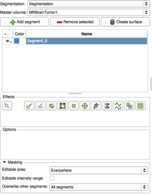
Segmentation: Choose the segmentation to edit
Master volume: Choose the volume to segment. The master volume can be changed at any time during the segmentation process, safely
Add/Remove Segment: Click Add to create a new segment. Select the segment you would like to delete then hit remove.
Create Surface: Display your segmentation in the 3D Viewer. This is a toggle button. When turned on the surface is created and updated automatically as the user is segmenting. When turned off, the conversion is not ongoing so the segmentation process is faster.
Segments Table: Displays your segments. Click the eye icon to show or hide the segment. Click and hold the button for advanced options (Show in 3D, Show in 2D as fill, Show in 2D as outline)
Effects: Select the desired effect here. See below for more information about each effect.
Options: Options for the selected effect will be displayed here.
Masking: These options allow you to define the editable areas and whether or not certain segments can be overwritten.
- Editable area: Changes will only appear within the selected area. Options include: Inside All Segments, Inside All Visible Segments, Outside All Segments, Outside All Visible, Everywhere
- Editable intensity range: Only areas within the selected intensity range will show changes that are made to the segmentation
- Overwrite other segments: Select which segments will be overwritten rather than overlapped. Options include: All segments, Visible Segments and None
Effects
Effects operate either by clicking the Apply button in the GUI or by clicking and/or dragging in the slice view. For operations where you use the GUI, the target label map is the one in the Red slice viewer. Otherwise the target is based on which slice viewer you click in. To use, select the label value for the tools to work on. Clicking on the colored box will provide a pop-up with a selection of labels.
 Paint
Paint
Paint on the selected segment with a round brush.
- Pick the radius (in millimeters) of the brush to apply
- Left click to apply single circle
- Left click and drag to draw a curve
- A trace of circles is left which are applied when the mouse button is released
- Sphere mode applies the radius to slices above and below the current slice.
The 'smudge' option can be used when working on the boundary between two or more regions. In this mode, the label color is set to the value of the labelmap where the first left click occurs. This mode allows you to quickly switch between colors.
 Draw
Draw
Draw segment outline in slice viewers.
- Left click to lay individual points of an outline
- Left drag to lay down a continuous line of points
- 'x' key to delete the last point added
- Right click or 'a' key to apply outline to label map
 Erase
Erase
Left-click and drag in slice or 3D viewers to erase from the current segment with a round brush. The radius can be adjusted. Additional brush modes include sphere brush and pixel mode.
 Level Tracing
Add uniform intensity region to selected segment. As you move the mouse, the current background voxel is used to find a closed path that follows the same intensity value back to the starting point within the current slice. Pressing the left mouse button filles the path according to the current labeling rules.
 Rectangle
Add a rectangular area to the selected segment
- Left click and drag to sweep our
 Margin
Grow or shrink the selected segment by a specified margin size. A positive margin size makes the segment grow while a negative margin size makes the segment shrink.
 GrowCut
GrowCut is a powerful algorithm that uses example segmentation to create a full segmentation of the volume. You can use multiple label colors to define regions that represent parts of anatomical structures and then let the GrowCut algorithm seek out a best labeling for adjacent pixel so they match your example.
To use this, you first define your example segmentation using the normal paint or draw tools as described above. Define at least two structure classes and then click Apply. If you are not satisfied with the result, use the Undo button to go back and modify your example.
See the Grow Cut documentation for more details.
Also see the Fast GrowCut documentation. This is an effect that can be added by downloading the extension. It requires memory but is a fast implementation of the GrowCut method
 Threshold
- Use Threshold to determine a threshold range and click on Use for Paint
- Change into Paint or Draw and click on the Threshold button
- begin painting/drawing
Only voxels where the background value is within the threshold range will be set to the new label value. The range is inclusive, so for example if the minimum is zero to ten, all pixels zero and above but less than or equal to ten will be included.
 Smoothing
Smooths the selected segment by removing extrusions and filling small holes.
There are four smoothing modes available:
- Median: reduces noise while preserving edges
- Gaussian: reduces image detail
- Opening: removes extrusions
- Closing: fills small holes
 Logical Operators
Apply logical operators on a segment or combine it with other segments. Operations include:
- Copy from segment: Replace the selected segment by the modifier segment
- Union with segment: Add modifier segment to current segment
- Intersection with segment: only keeps those regions in the select segment that are common with the modifier segment
- Subtract Segment: Subtract region of modifier segment from the selected segment
- Clear: Clears the selected segment
- Fill: Completely fills the selected segment
 Identify Islands
Use this tool to create a unique label value for each connected region in the current label map. Connected regions are defined as groups of pixels which touch each other but are surrounded by zero valued voxels. If FullyConnected is selected, then only voxels that share a face are counted as connected; if unselected, then voxels that touch at an edge or a corner are considered connected.
Note: Be aware that all non-zero label values labels values are considered equal by this filter and that the result will renumber the resulting islands in order of size. Note: The output label values use the currently selected color table, but the names assigned to islands are arbitrary. Label values are assigned in order of the size of the island starting with 1. The value of 0 is assigned to the background.
Keystrokes
Movement
- f - move to next slice
- b - move to previous slice
- h - toggle the crosshair and put it into navigator mode
Effect Selection for Editor module
- Escape - cancel current effect
- p - select Paint effect
- d - select Draw effect
- e - select Eraser effect
- r - select Rectangle effect
Draw Effect Keystrokes
- a or Enter or Right-click - apply the current outline
- x - delete last point added
Segment Editor Keystrokes
- Escape - cancel current effect
- 1 - select Paint effect
- 2 - select Draw effect
- 3 - select Eraser effect
- 4 - select Level tracing
- 5 - select Grow from seeds effect
- 6 - select Fill between slices effect
- 7 - select Threshold effect
- 8 - select Margin effect
- 9 - select Smoothing effect
- 0 - select Scissors effect
- Shift + 1 - select Islands effect
- Shift + 2 - select Logical operators effect
- Shift + Mousewheel - adjust brush/eraser size


