Difference between revisions of "Modules:StochasticTractography-Documentation-3.4"
| Line 38: | Line 38: | ||
{| | {| | ||
| + | | | ||
* Step 1 : smooth using a Half Width Full Maximum gaussian filter, | * Step 1 : smooth using a Half Width Full Maximum gaussian filter, | ||
|[[Image:smooth2.png|thumb|500px|Smoothing step]] | |[[Image:smooth2.png|thumb|500px|Smoothing step]] | ||
| Line 43: | Line 44: | ||
{| | {| | ||
| + | | | ||
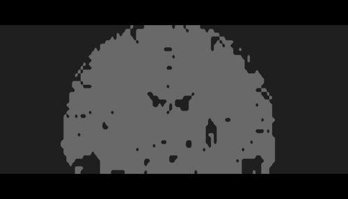
* Step2 : generate a brain mask, | * Step2 : generate a brain mask, | ||
|[[Image:mask2.png|thumb|500px|Brain mask step]] | |[[Image:mask2.png|thumb|500px|Brain mask step]] | ||
| Line 48: | Line 50: | ||
{| | {| | ||
| + | | | ||
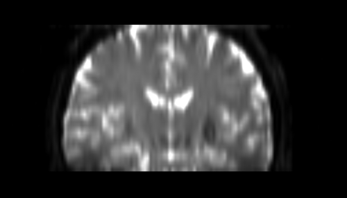
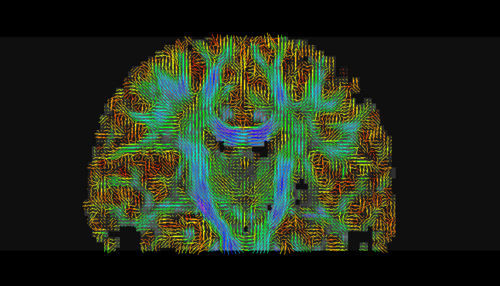
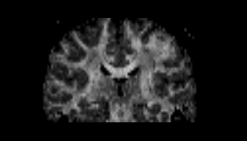
* Step3 : create a DTI (Diffusion Tensor Image) tensor with standard measures like fractional anisotropy (FA), mode and trace, | * Step3 : create a DTI (Diffusion Tensor Image) tensor with standard measures like fractional anisotropy (FA), mode and trace, | ||
|[[Image:tensor2.png|thumb|500px|Tensor step]] | |[[Image:tensor2.png|thumb|500px|Tensor step]] | ||
| + | | | ||
** produce different measures based on the tensor like fractional anistropy (FA), mode and trace | ** produce different measures based on the tensor like fractional anistropy (FA), mode and trace | ||
|[[Image:fa2.png|thumb|500px|Tensor step: FA]] | |[[Image:fa2.png|thumb|500px|Tensor step: FA]] | ||
| Line 57: | Line 61: | ||
{| | {| | ||
| + | | | ||
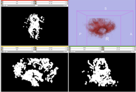
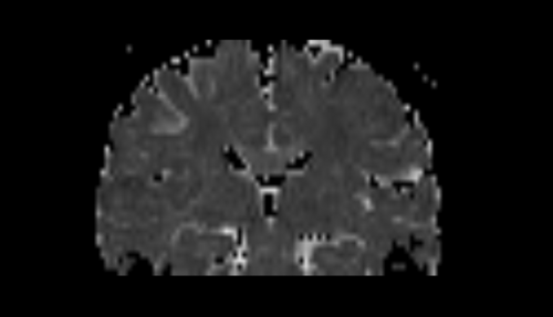
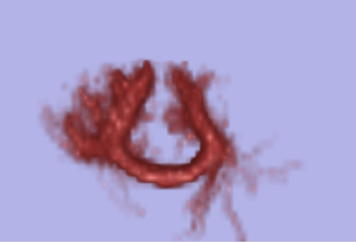
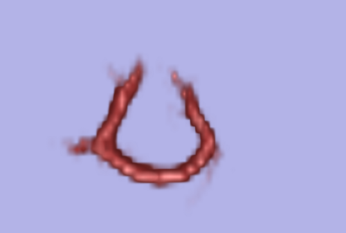
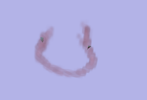
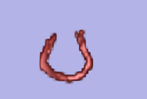
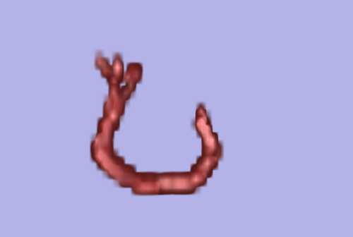
* Step4 : run tractography and produce connection maps in case 2 ROIs are given | * Step4 : run tractography and produce connection maps in case 2 ROIs are given | ||
** showing union and intersection of both maps from region A to region B and B to A | ** showing union and intersection of both maps from region A to region B and B to A | ||
|[[Image:AorB2.png|thumb|500px|Union of A to B and B to A]] | |[[Image:AorB2.png|thumb|500px|Union of A to B and B to A]] | ||
|[[Image:AandB2.png|thumb|500px|Intersection of A to B and B to A]] | |[[Image:AandB2.png|thumb|500px|Intersection of A to B and B to A]] | ||
| + | | | ||
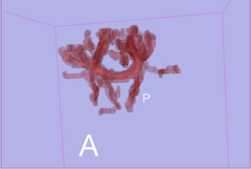
** showing only tracts connecting A to region B and B to A | ** showing only tracts connecting A to region B and B to A | ||
|[[Image:connectAB2.png|thumb|500px|ROI filtering]] | |[[Image:connectAB2.png|thumb|500px|ROI filtering]] | ||
Revision as of 19:30, 15 April 2009
Home < Modules:StochasticTractography-Documentation-3.4Return to Slicer 3.4 Documentation
Module Name
Stochastic Tractography
General Information
Module Type & Category
Type: Interactive
Category: DTI
Authors, Collaborators & Contact
- Author: Julien von Siebenthal
- Contributor: Steve Pieper
- Contact: jvs@bwh.harvard.edu
Module Description
As a main purpose, the stochastic tractography module helps to evaluate connectivity between two regions of the Grey Matter of the brain using ROIs (Region Of Interest) as inputs. These ROIs define grey matter regions ensuring a specific neurophysiological function. Extensively, study involving more than two regions could still be done by pairing the regions two by two and computing them separetely to finally gather the results.
Usage
- want to study fiber paths from a single region of interest (ROI)
- want to evaluate connectivity between two ROIs
Description
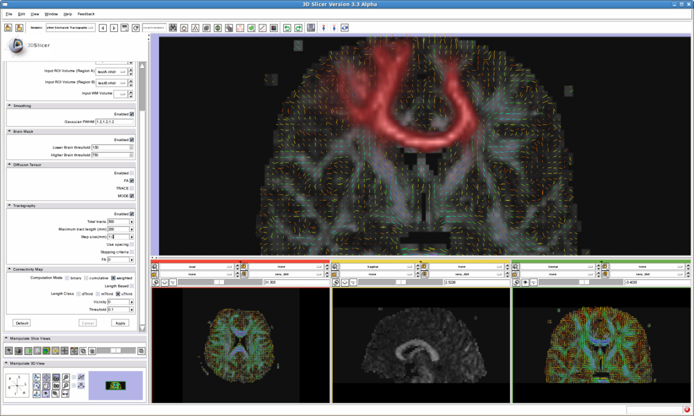
The stochastic tractography module interface implements the following workflow:
|
|
|
|
|
|
Quick Tour of Features and Use
List all the panels in your interface, their features, what they mean, and how to use them. For instance:
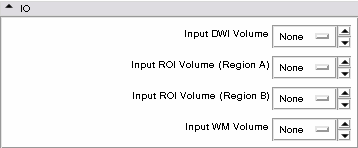
- IO panel:
- Smoothing panel:
- Brain Mask panel:
- Diffusion Tensor panel:
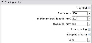
- Tractography panel:
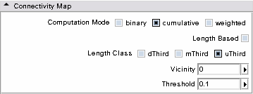
- Connectivity Map panel:
Development
Dependencies
Volumes
Known bugs
Follow this link to the Slicer3 bug tracker.
Usability issues
Follow this link to the Slicer3 bug tracker. Please select the usability issue category when browsing or contributing.
Source code & documentation
More Information
Acknowledgment
National Alliance for Medical Image Computing (NAMIC), funded by the National Institutes of Health through the NIH Roadmap for Medical Research, Grant U54 EB005149 (to Ron Kikinis, Marek Kubicki).
References
- Björnemo M, Brun A, Kikinis R, Westin CF. Regularized stochastic white matter tractography using diffusion tensor MRI. In Fifth International Conference on Medical Image Computing and Computer-Assisted Intervention (MICCAI'02). Tokyo, Japan, 2002;435-442.
- Friman, O., Farneback, G., Westin CF. A Bayesian Approach for Stochastic White Matter Tractography. IEEE Transactions on Medical Imaging, Vol 25, No. 8, Aug. 2006
- Shenton, M.E., Ngo, T., Rosenberger, G., Westin, C.F., Levitt, J.J., McCarley, R.W., Kubicki, M. Study of Thalamo-Cortical White Matter Fiber Tract Projections in Schizophrenia Using Diffusion Stochastic Tractography. Poster presented at the 46th Meeting of the American College of Neuropsychopharmacology, Boca Raton, FL, December 2007.
