Difference between revisions of "Slicer3:Module:BinaryErodeOperations-Documentation"
| (12 intermediate revisions by the same user not shown) | |||
| Line 1: | Line 1: | ||
| + | [[Documentation|Return to Slicer Documentation]] | ||
| + | |||
==Binary Erode Operations== | ==Binary Erode Operations== | ||
| Line 10: | Line 12: | ||
===Module Type&Category=== | ===Module Type&Category=== | ||
| − | This module is for performing | + | This module is for performing erosion on binary images. The type of this module is CLI and is in the category of Segmentation of Slicer 3. |
===Authors, Collaborators & Contact=== | ===Authors, Collaborators & Contact=== | ||
| Line 32: | Line 34: | ||
{| | {| | ||
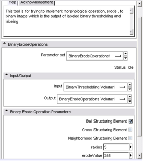
| − | |[[Image:GUIPanelErode.PNG|thumb|280px|The GUI panel for | + | |[[Image:GUIPanelErode.PNG|thumb|280px|The GUI panel for BinaryErodeOperations Module after binary thresholding]] |
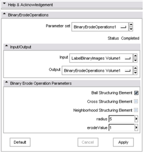
| + | |[[Image:GUIPanelErodeLabel.PNG|thumb|280px|The GUI panel for BinaryErodeOperations Module after LabelBinaryImages Module]] | ||
|} | |} | ||
| Line 47: | Line 50: | ||
===The Problems=== | ===The Problems=== | ||
| − | In this module, the problems were stemmed from the choices of structuring element, the radius size of them. The performance of erosion depends on the properties of structuring element. The reason is that sometimes the shape of the binary image can not be preserved after erosion. For instance, the spheres data I used became had like a square shape if I used other structuring elements instead of ball structuring element. Therefore, ball structuring element was used in BinaryErodeOperations Module. However, if user wants to try others, the default value for structuring element should be changed from the code file. I could not also do it interactive. | + | In this module, the problems were stemmed from the choices of structuring element, the radius size of them. The performance of erosion depends on the properties of structuring element. The reason is that sometimes the shape of the binary image can not be preserved after erosion. For instance, the spheres data I used became had like a square shape if I used other structuring elements instead of ball structuring element. Therefore, ball structuring element was used in BinaryErodeOperations Module. However, if user wants to try others, the default value for structuring element should be changed from the code file. I could not also do it interactive. The difference between the performance of structuring elements can be seen in ''Screen shots'' section. |
| − | In addition to the problems, I encountered with a problem when I used binary labeled image as an input to BinaryErodeOperations Module. The problem is that I could not create a label map by using Editor Module in Slicer 3. The reason may be due to the output I have after LabelBinaryImages Module. The inside pixel is 1 and the outside pixel is 0 for the binary labeled images. The erosion worked well these images but at the end of the erosion | + | In addition to the problems, I encountered with a problem when I used binary labeled image as an input to BinaryErodeOperations Module. The problem is that I could not create a label map by using Editor Module in Slicer 3. The reason may be due to the output I have after LabelBinaryImages Module. The inside pixel is 1 and the outside pixel is 0 for the binary labeled images. The erosion worked well these images but at the end of the erosion, I could not define two different labels by using Editor Module. Therefore, without having different labels, I could not continue on dilation because in dilation my aim is to see different labeled images touched each other but not overwritten after several steps. However, the failure in creating labels is the reason of not using the binary labeled images for my project. The detailed information is given in the section of ''the Problems'' in [[Slicer3:Module:LabelBinaryImages-Documentation|LabelBinaryImages]]. |
===Screen shots=== | ===Screen shots=== | ||
| Line 57: | Line 60: | ||
|[[Image:AfterLabelChange.PNG|thumb|280px|Creating two different labels after erosion processes]] | |[[Image:AfterLabelChange.PNG|thumb|280px|Creating two different labels after erosion processes]] | ||
|[[Image:AfterModelMaker.PNG|thumb|280px|Creating 3D model of separated and different labeled binary images by using Model Maker Module]] | |[[Image:AfterModelMaker.PNG|thumb|280px|Creating 3D model of separated and different labeled binary images by using Model Maker Module]] | ||
| + | |[[Image:Erosion1.png|thumb|300px|The results of erosion;neighborhood, ball, cross in order]] | ||
|} | |} | ||
Although the first figure shows four steps in erosion, it took 7 steps in order to make them totally separate. The ball structuring element with radius 5 was used in erosion process. | Although the first figure shows four steps in erosion, it took 7 steps in order to make them totally separate. The ball structuring element with radius 5 was used in erosion process. | ||
| + | The last figure shows the different results by using three different structuring elements:neighborhood, ball, cross in order. It can be observed that the shape is better when ball structuring element is used compared to the cases of using either neighborhood or cross structuring element. | ||
==MORE INFORMATION== | ==MORE INFORMATION== | ||
Latest revision as of 18:29, 28 August 2008
Home < Slicer3:Module:BinaryErodeOperations-DocumentationReturn to Slicer Documentation
Binary Erode Operations
GENERAL INFORMATION
Module Type&Category
This module is for performing erosion on binary images. The type of this module is CLI and is in the category of Segmentation of Slicer 3.
Authors, Collaborators & Contact
- Author: Bike Kilic, MSc student in Northeastern University
- Contact: kilicbike@gmail.com
Module Description
This module aims to perform erosion method in order to make the two different objects separate in a given image. After separating them, the next step will be creating a label map and changing the labels to specify different regions.
This method uses a structuring element in order to cover the object border with given foreground value. It shrinks the object with this structuring element. For this project, the structuring element is ball structuring element with a radius size which is defined by the user.
For example, the results given in Screen shots part, the structuring element is ball structuring element with radius 5. It took 7 iterations in order to get the desired output before creating different labels.
The input of this module is the output of the BinaryThresholding( or LabelBinaryImages) module at the beginning. For the following iterations, the input is the eroded binary image from the previous iteration.
USAGE
Quick Tour of Features and Use
As seen above, the first figure shows the GUI panel if the user implements BinaryThresholding Module before erosion, whereas the second one shows the GUI panel of BinaryErodeOperations module in the case of using LabelBinaryImages module before erosion.
DEVELOPMENT
Dependencies
The BinaryErodeOperations Module uses four ITK classes. One of them is for binary erosion, which is called itkBinaryErodeImageFilter [1]. Three of ITK classes which are included are used to create structuring elements. For ball structuring element, itkBinaryBallStructuringElement[2]; for cross structuring element itkBinaryCrossStructuringElement[3] and for neighborhood structuring element itkNeighborhood[4] are added.
In this project, for erosion the ball structuring element has been chosen.
The Problems
In this module, the problems were stemmed from the choices of structuring element, the radius size of them. The performance of erosion depends on the properties of structuring element. The reason is that sometimes the shape of the binary image can not be preserved after erosion. For instance, the spheres data I used became had like a square shape if I used other structuring elements instead of ball structuring element. Therefore, ball structuring element was used in BinaryErodeOperations Module. However, if user wants to try others, the default value for structuring element should be changed from the code file. I could not also do it interactive. The difference between the performance of structuring elements can be seen in Screen shots section.
In addition to the problems, I encountered with a problem when I used binary labeled image as an input to BinaryErodeOperations Module. The problem is that I could not create a label map by using Editor Module in Slicer 3. The reason may be due to the output I have after LabelBinaryImages Module. The inside pixel is 1 and the outside pixel is 0 for the binary labeled images. The erosion worked well these images but at the end of the erosion, I could not define two different labels by using Editor Module. Therefore, without having different labels, I could not continue on dilation because in dilation my aim is to see different labeled images touched each other but not overwritten after several steps. However, the failure in creating labels is the reason of not using the binary labeled images for my project. The detailed information is given in the section of the Problems in LabelBinaryImages.
Screen shots
Although the first figure shows four steps in erosion, it took 7 steps in order to make them totally separate. The ball structuring element with radius 5 was used in erosion process. The last figure shows the different results by using three different structuring elements:neighborhood, ball, cross in order. It can be observed that the shape is better when ball structuring element is used compared to the cases of using either neighborhood or cross structuring element.
MORE INFORMATION
Future work
In this module, what we should improve is using effective structuring element. ITK has four different structuring elements which I have tried three of. A structuring element which stores an information of the shape of the whole image may be effective in this goal. On the other hand, if the data is noisy, any smoothing or enhancement method should be performed before erosion.
References
- Gu L., Seminar Series on Advanced Medical Image Processing, Mathematical Morphology(1), 2002.
- Ibanez L.,ITK Architecture, ITK Basic Filters, 2006.
- Ibanez L.,ITK Arcitecture, ITK Segmentation Methods, 2000.
- Ibanez L., Schroeder W.,Ng L. & Cates J., The ITK Software Guide Second Edition Updated for ITK Version 2.4, 2005.
- Lehmann G., Binary Morphological closing and opening image filters, 2006.
- Lehmann G., Improving features and performance of binary erode and dilate filters, 2006.
- Vleeschouwer C., Morphology, 2007.[5]


